- Mailing Lists
- in
- Network Protocols Run the Internet
Archives
- By thread 5319
-
By date
- June 2021 10
- July 2021 6
- August 2021 20
- September 2021 21
- October 2021 48
- November 2021 40
- December 2021 23
- January 2022 46
- February 2022 80
- March 2022 109
- April 2022 100
- May 2022 97
- June 2022 105
- July 2022 82
- August 2022 95
- September 2022 103
- October 2022 117
- November 2022 115
- December 2022 102
- January 2023 88
- February 2023 90
- March 2023 116
- April 2023 97
- May 2023 159
- June 2023 145
- July 2023 120
- August 2023 90
- September 2023 102
- October 2023 106
- November 2023 100
- December 2023 74
- January 2024 75
- February 2024 75
- March 2024 78
- April 2024 74
- May 2024 108
- June 2024 98
- July 2024 116
- August 2024 134
- September 2024 130
- October 2024 141
- November 2024 171
- December 2024 115
- January 2025 216
- February 2025 140
- March 2025 220
- April 2025 233
- May 2025 239
- June 2025 303
- July 2025 131
Network Protocols Run the Internet
Network Protocols Run the Internet
This is a sneak peek of today’s paid newsletter for our premium subscribers. Get access to this issue and all future issues - by subscribing today. Latest articlesIf you’re not a subscriber, here’s what you missed this month:
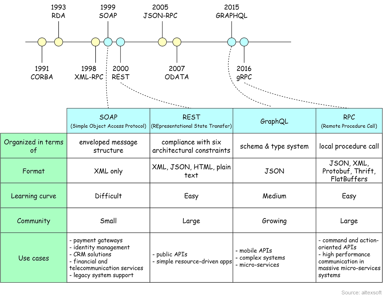
To receive all the full articles and support ByteByteGo, consider subscribing: In distributed systems, data is sent over the network using various network protocols. As an application developer, this often seems like a block box until an issue arises. In this issue, we’ll explain how common network protocols work, where they are used in distributed systems, and how we troubleshoot common problems. We’ll cover some popular interview questions as well. For example:
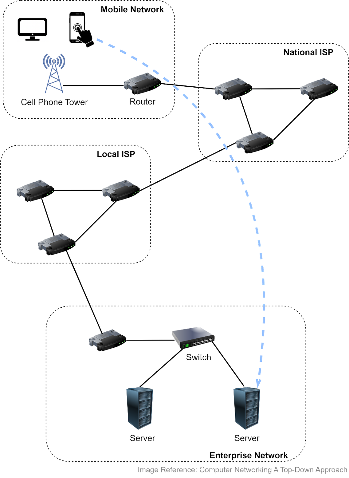
Let’s first look at where the network protocols are used. Internet and the OSI ModelThe Internet links a wide range of computing devices around the world. We can get a rough idea from the diagram below. Suppose we access a website from a smartphone or laptop, which connects to a cellular tower. The tower connects to a router, which then accesses the internet via Internet Service Providers (ISPs). Packets are forwarded to a local ISP, then to the network hosting the website. Once the packets reach the company network, they go through a link-layer switch and reach the appropriate server. Both routers and link-layer switches are packet switches, and their job is to forward packets. The difference is that routers are usually used in the network core to connect multiple networks, while link-layer switches are used in access networks (the network that physically connects an end system to an edge router), connecting several devices in a single network.
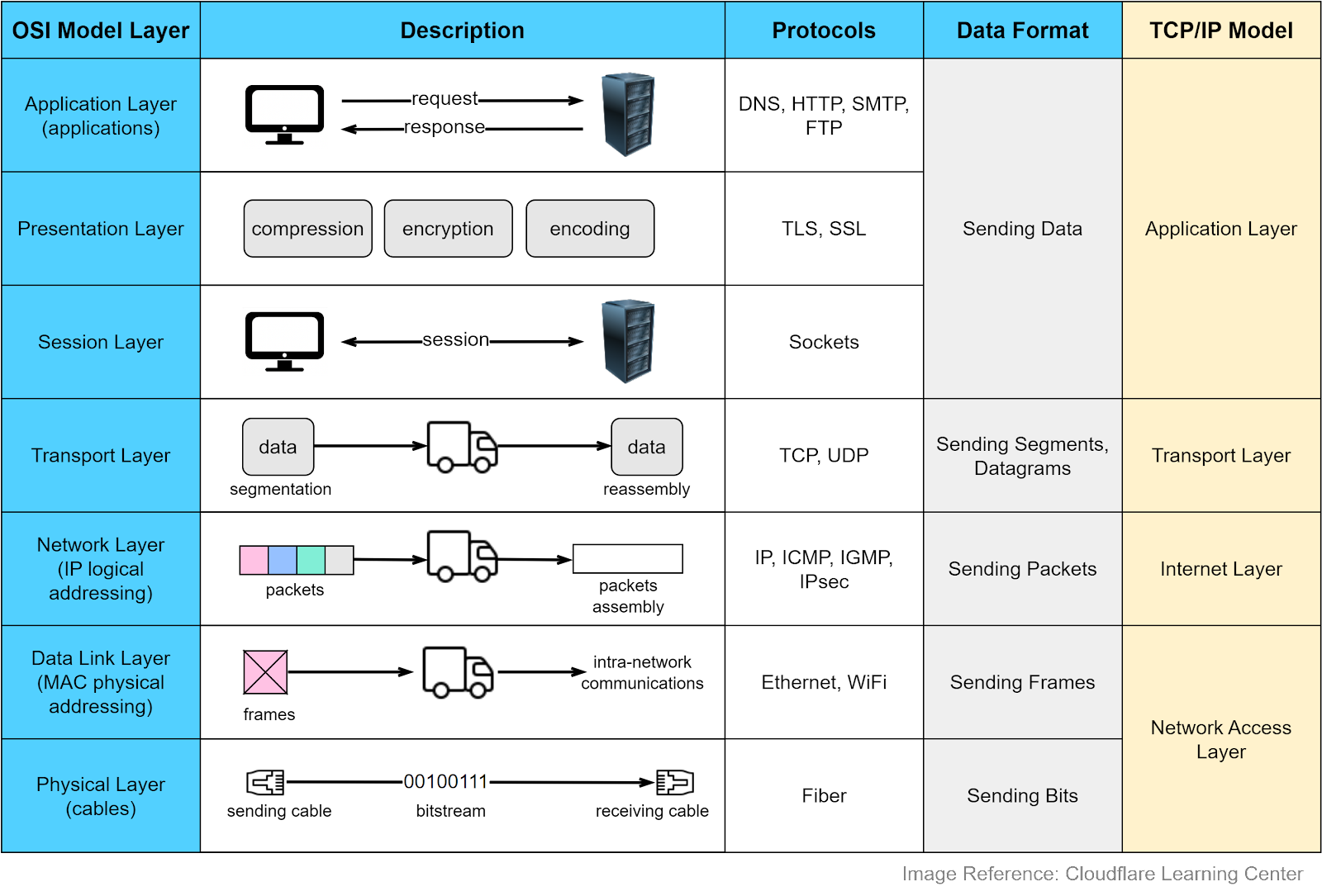
Why do we need network protocols? Internet-connected devices need to communicate in a language that they can understand. Various computer systems communicate with each other using a standard specified by the OSI (Open Systems Interconnection) model. The OSI model has seven abstract layers, each with distinct responsibilities and protocols. The diagram below shows what each layer does in the OSI model. Each intermediate layer serves a class of functionality to the layer above it and is served by the layer below it. Let’s review them.
The application layer is the closest to the end users. Most applications reside in this layer. We request data from a backend server without needing to understand data transmission specifics. Protocols in this layer include HTTP, SMTP, FTP, DNS, etc. We will cover them later.
This layer handles data encoding, encryption, and compression, preparing data for the application layer. For example, HTTPS leverages TLS (Transport Layer Security) for secure communications between clients and servers.
This layer opens and closes the communications between two devices. If the data size is large, the session layer sets a checkpoint to avoid resending from the beginning.
This layer handles end-to-end communication between the two devices. It breaks data into segments at the sender’s side and reassembles them at the receiver’s. There is flow control in this layer to prevent congestion. Key protocols in this layer are TCP and UDP, which we’ll discuss later.
This layer enables data transfer between different networks. It further breaks down segments or datagrams into smaller packets and finds the optimal route to the final destination using IP addresses. This process is known as routing.
This layer allows data transfer between devices on the same network. Packets are broken down into frames, which are confined to a local area network.
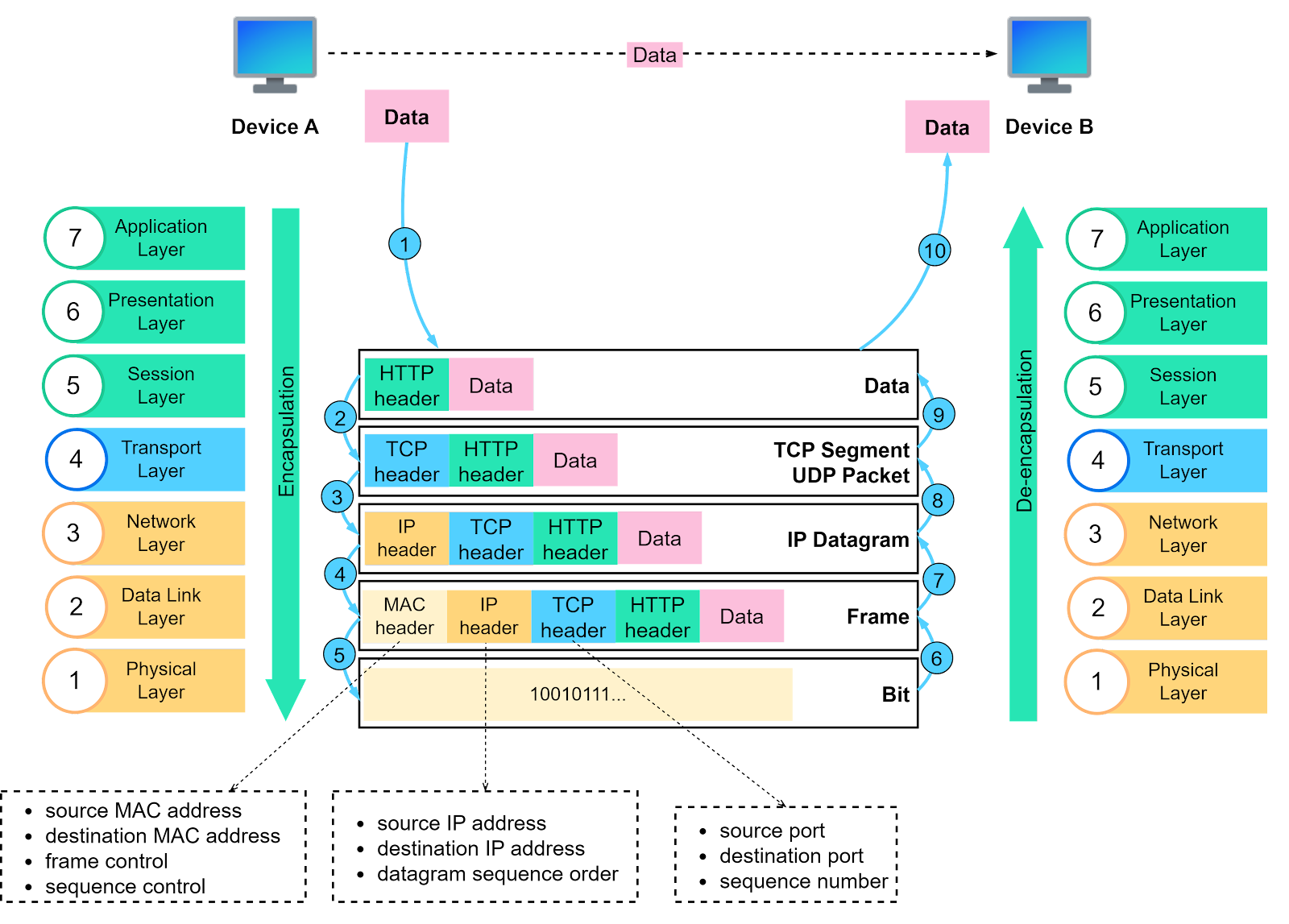
This layer sends bitstreams over cables and switches, making it closely associated with the physical connection between devices. Compared to the OSI model, the TCP/IP model only has 4 layers. When discussing layers, it’s important to specify the context. Now that we understand the responsibilities of each layer, let’s summarize the data transfer process using the following diagram. This is called encapsulation and decapsulation. Encapsulation involves adding headers to the data as it travels towards its destination. Decapsulation removes these headers to retrieve the original data.
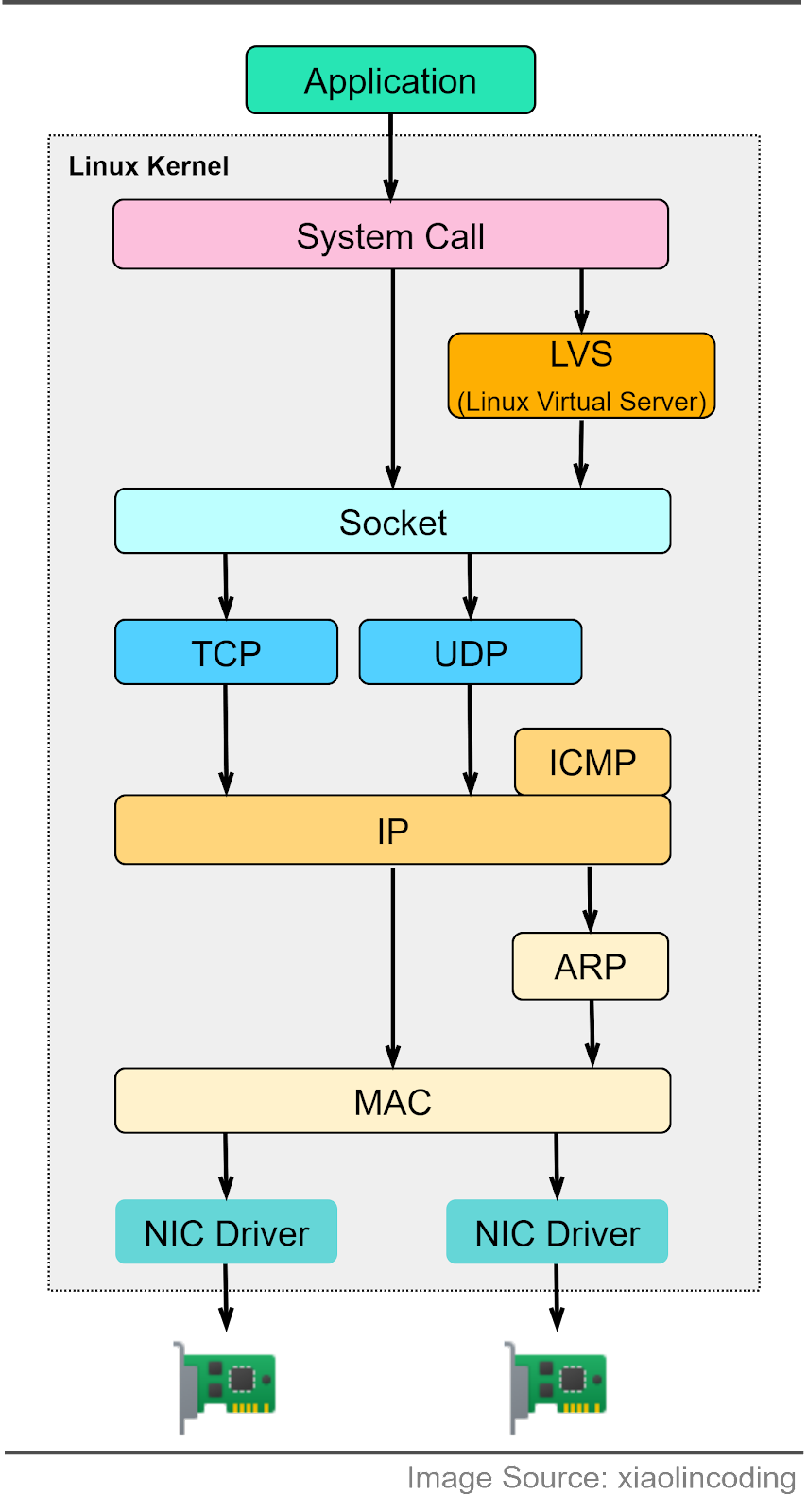
Step 1: When Device A sends data to Device B over the network using HTTP, an HTTP header is initially added at the application layer. Step 2: A TCP or a UDP header is added to the data. It is encapsulated into TCP segments at the transport layer. The header contains the source port, destination port, and sequence number. Step 3: The segments are then encapsulated with an IP header at the network layer. The IP header contains the source and destination IP addresses. Step 4: An MAC header is added to the IP datagram at the data link layer, containing the source and destination MAC addresses. Step 5: The encapsulated frames are sent to the physical layer and sent over the network as bitstreams. Steps 6-10: When Device B receives the bits from the network, it initiates the de-encapsulation process, which is the reverse of the encapsulation process. Headers are removed layer by layer, until Device B can access the original data. Note that each layer uses the headers for processing instructions and does not need to unpack the data from the previous layer. How do the OSI model layers map to a Linux server implementation? The diagram below provides more detail. The Linux network protocol stack aligns closely with the 4-layer TCP/IP model. The application sends data to the socket via system calls. The socket serves an abstraction for the communication endpoint. The socket layer accepts the data and passes it to the transport and network layer. The data eventually reaches the Network Interface Card (NIC) and is sent over the network.
In the next section, we will explore the common network protocols used when visiting an eCommerce website... Keep reading with a 7-day free trialSubscribe to ByteByteGo Newsletter to keep reading this post and get 7 days of free access to the full post archives. A subscription gets you:
© 2023 ByteByteGo
|
by "ByteByteGo" <bytebytego@substack.com> - 11:41 - 15 Jun 2023